Interior Gateway Protocols (IGPs)
IGPs are used for routing within an autonomous system (AS) or an internal network. They help routers exchange routing information and make routing decisions within the boundaries of the AS. Some common IGPs include Routing Information Protocol (RIP), Open Shortest Path First (OSPF), and Intermediate System to Intermediate System (IS-IS). IGPs are typically used to facilitate communication and routing between routers within a single organization or network.
Key characteristics of IGPs:
- Used for routing within a single autonomous system or internal network.
- Exchange routing information between routers within the same network domain.
- Typically focus on factors such as shortest path or link cost when making routing decisions.
- Examples include RIP, OSPF, IS-IS.
Exterior Gateway Protocols (EGPs):
EGPs, on the other hand, are used for routing between autonomous systems (ASes) or different networks operated by separate organizations. Their primary purpose is to exchange routing information between different ASes on the internet. The most widely used EGP is the Border Gateway Protocol (BGP), which enables routers to exchange routing information across multiple networks and make routing decisions that span across AS boundaries.
Key characteristics of EGPs:
- Used for routing between autonomous systems or different networks.
- Exchange routing information between routers in different ASes.
- Focus on factors such as AS path, policies, and external reachability when making routing decisions.
- Examples include Border Gateway Protocol (BGP).
In summary, IGPs are employed for internal routing within a network or autonomous system, while EGPs are used for routing between autonomous systems or different networks. The scope, routing decision factors, and the protocols used are the primary distinctions between these two types of gateway protocols.
]]>OSPF IN DOWN STATE
Hello packets are very important parameters in establishing adjacency in any routing protocol not only in OSPF. Now, if no hello packets have been received from the neighbor and the dead timer interval has expired, OSPF is in DOWN state. The first OSPF neighbor state is “DOWN” state. It usually happens on Non-Broadcast MultiAccess (NBMA) networks and Non-Broadcast Point-to-Multipoint networks where neighbor is manually configured.
OSPF IN ATTEMPT STATE
“ATTEMPT” state only exist on NBMA networks. The router is sending Hello packets but these are not received by its peer.
OSPF IN INIT STATE
This is the same with the “CONNECT” state of BGP. When OSPF is in INIT state, that means that the router sees the Hello packets from the neighbor but the two way communication is not yet established. The receiving router should list its own router ID to acknowledge that it has a received a valid Hello packet.
It is not good to see a neighbor that stays on “INIT” state for a long time. There are many reasons why OSPF neighbor adjacency is stuck in “INIT” state.
- It can be a configuration/mismatch on the following parameters like Hello/Dead Timers, network mask, and Area ID.
- It can be an authentication issue. When authentication is used, make sure that authentication type and authentication key matches on both ends.
- For some reason, an access-list for OSPF multicast address 224.0.0.5 is being denied, this also causes the router to stay in “INIT” state. This address plays an important role in the two-way communication because this is the destination address of Hello packets.
- If you are configuring static frame-relay and/or dialer map and you forgot the “broadcast” keyword, it would also be an issue and make you stuck in this state. The use of the “broadcast” keyword is required if broadcast and multicast traffic is to be sent over the specified DLCI.
- Finally, it can be a Cisco bug (Cisco bug ID CSCdj01682). Try to issue “show ip ospf interface” command and check the “Neighbor Count” and “Adjacent Neighbor Count.” If the “Adjacent Neighbor Count” is higher than the “Neighbor Count” then it could be a bug.
OSPF IN 2WAY STATE
At this stage, two-way communication has been established. The router has seen its own router ID in the neighbor field of the neighbor’s packet. Do not be alarm if your routers are in “2WAY” state. In a multiaccess segments where DR and BDR are present, all DROTHERS (Not DR/Not BDR) will stay in “2WAY” state. This is normal and expected behavior as those routers will synchronize their database with DR and/or BDR only.
When there is no issue, the router checks if it is already listed as neighbor in its peer. If it is, it resets the dead timer and neighbor relationship is already formed. If not, it goes to “EXSTART/EXCHANGE” state.
OSPF IN EXSTART STATE
This is the state when the bidirectional communication has been established and in multiaccess segments, where DR and BDR election is completed, the routers enter the “EXSTART” state and start the Master/Slave relationship. In a Master/Slave relationship, it is determined by highest priority and/or router ID.
OSPF IN EXCHANGE STATE
Once the Master/Slave relationship is negotiated, the Master starts the exchange of Database Descriptor. After Master sends its DBD, the Slave sends its own DBD. If no issue occurs, it goes to “LOADING” state. However, if OSPF is stuck in “EXSTART/EXCHANGE” state the main reason is a mismatched MTU. It usually occurs when connecting a Cisco router to non-Cisco router.
A router with the higher MTU continues to accept the DBD packet of the router with the lower MTU. It will be stuck in “EXCHANGE” state. On the other hand, the router with the lower MTU will stay in “EXSTART” state. It will discard the DBD packets and will continue to retransmit the initial DBD
OSPF IN LOADING STATE
Once DBDs are acknowledged and reviewed, it now goes to “LOADING” state. OSPF stuck in “LOADING” state and generates OSPF-4-BADLSA error message is not normal. This means that LSA being exchanged is corrupted. Contact Cisco TAC support.
OSPF IN FULL STATE
IN “FULL” state, neighbors have formed and they have now the same Link State Database (LSDB).
]]>| Version Number | Type | Packet length |
| Router ID | ||
| Area ID | ||
| Checksum | Authentication Type | |
| Authentication | ||
| Message Body | ||
VERSION
OSPF has two versions: Version 1 (RFC 1131) and Version 2. I’m not sure if anyone has ever tried the version 1. It was published in the year 1989 and it was immediately replaced by version 2. I tried to check the RFC to know more about this but this is what I got:
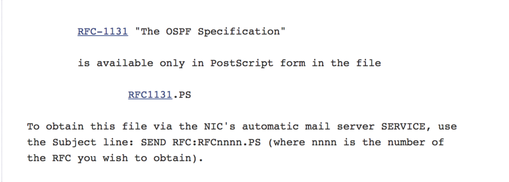
I cannot differentiate the two versions because right now when we say OSPF (for IPv4), that means we are referring to version 2.
TYPE
There are 5 different OSPF packet types: Type 1 – Hello packet, Type 2- Database Descriptor packet, Type 3 – Link State Request packet, Type 4 – Link State Update packet, and Type 5 – Link State Acknowledgement packet. So if the field has a value of 3 that means it is a Link State Request packet type.
PACKET LENGTH
This is total OSPF packet length in bytes which also includes the OSPF packet header
ROUTER ID
This is the router ID of the source of the packet or the advertising router.
AREA ID
It is the area number to which the message belongs to and presented in dotted decimal.
CHECKSUM
This is the 16-bit standard IP checksum which includes calculation of the entire message except the authentication field.
AUTHENTICATION TYPE
There are 3 OSPF authentication type: 0 – no password, 1 – clear text, 3 – MD5 password. So when you use an MD5 password on the interface, this field should have a value of 3.
AUTHENTICATION
This is a 64-bit field used for data integrity.
]]>OSPF, like any other routing protocols, can agree or decline neighborship if their requirements are not met. Here are the adjacency requirements in order to form neighborship with OSPF:
1. same area ID
2. same subnet
3. same authentication type and authentication password
4. same hello and dead timers configuration
5. same area type
AREA ID
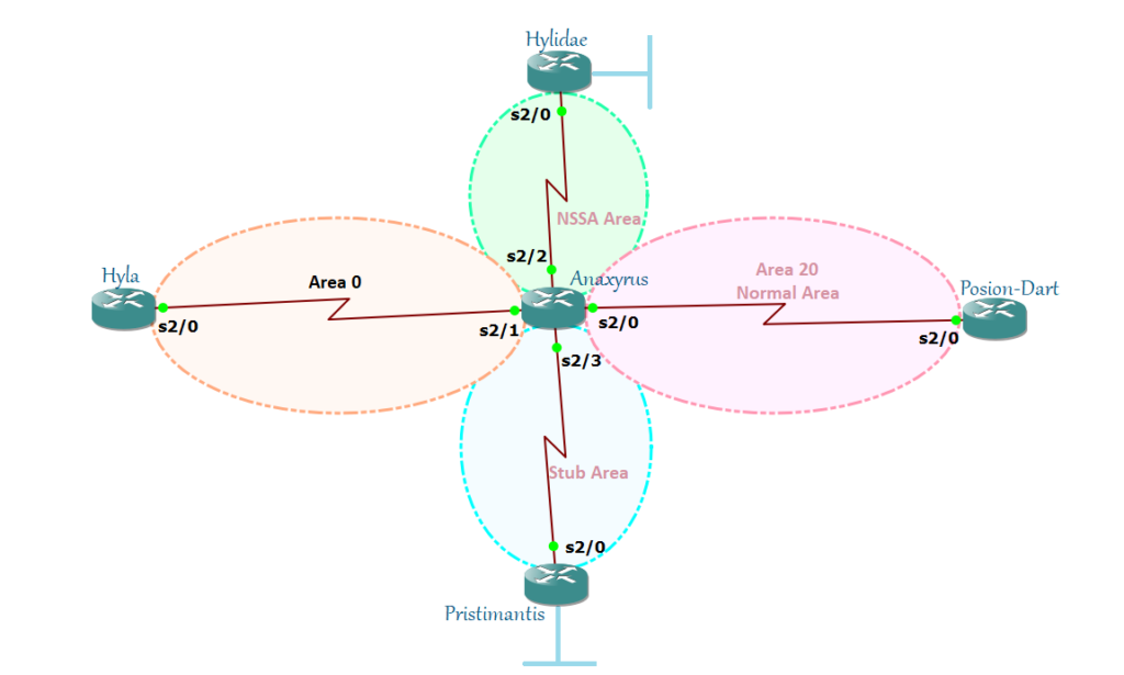
You configure Hyla s2/0 interface in area 1 and you configure Anaxyrus s2/1 interface in area 0. Do you think they are going to be neighbors? No. The first thing that OSPF checks is to form adjacencies with routers in the same area. It will be a mismatch if they are not on the same area.
Bringing back my topology on my previous post:
Anopheles(config)#router ospf 2
Anopheles(config-router)#network 192.168.12.0 0.0.0.255 area 0
Culex(config)#router ospf 1
Culex(config-router)#no network 192.168.12.0 0.0.0.255 area 0
Culex(config-router)#network 192.168.12.0 0.0.0.255 area 10
*Oct 18 23:54:34.411: %OSPF-4-ERRRCV: Received invalid packet: mismatch area ID, from backbone area must be virtual-link but not found from 192.168.12.2, Serial2/0
An invalid packet has seen indicating a mismatch area ID.
SUBNET MASK
A subnet mask is part of a Hello packet and one of the criteria that OSPF looks to form adjacencies. If you configure the two links in a different subnet, it will show a mismatch in hello packet parameters. This indicates that both links have different subnet masks. There is somehow a debate about this because this one should not be a mandatory requirement for OSPF adjacency. Subnet mask in point-to-point links is ignored and formed neighborship even connected links don’t have the same subnet mask. I will show you my lab example in my future posts.
AUTHENTICATION TYPE/AUTHENTICATION PASSWORD
As the name explicitly states, it is all about authentication configuration on OSPF. You must sure that if you have configured authentication on one link, you should have the same authentication configured on the remote link as well. And the authentication type should be the same: 0 – no password, 1 – plain text, and 2 – MD5 password. Lastly, the authentication key should be the same as well. I have a separated full-blown post regarding OSPF authentication.
HELLO AND DEAD TIMERS
EIGRP doesn’t care about its hello and dead timers but OSPF does. Hello and dead timers are OSPF Hello parameters and they must match or else adjacencies will not be formed. These two parameters are very crucial in determining if a neighbor still exists or not. A hello interval indicates how often the hello packet is sent while the dead timer indicates how long the neighbor router should wait for hello packets before declaring its link dead. The default hello interval for broadcast and point-to-point links is 10 seconds while dead timer is 40 seconds. And for the NBMA, point-to-multipoint, and point-to-multipoint NBMA hello timer default is 30 seconds while dead timer is 120 seconds. Did you notice that the dead timer is always four times the value of hello timer?
AREA TYPE
This is where OSPF area types like Stub, Totally Stubby, NSSA, and Totally NSSA come into play. Looking back on my previous post regarding area types, if you want to configure a certain area as Stub, Totally Stubby, NSSA, and Totally NSSA all the routers in this area should be in the same area type as well or else no adjacencies will be formed.
OSPF NETWORK TYPE
There are different OSPF network types: Broadcast, Non-Broadcast, Point-to-point, and Point-to-multipoint. Network type is not usually tagged as one of the mandatory requirements to form neighborship with OSPF. However, incompatible network types can’t form adjacency to each other. These network types can be further classified as DRs and non-DR types. Combining a DR and non-DR will not form OSPF adjacencies.
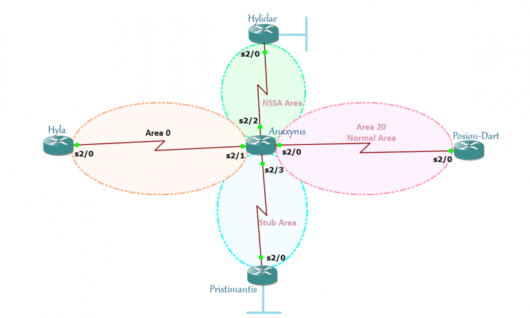
So here’s the Virtual Link. Virtual link is the solution to fix this broken OSPF design. You don’t need to physically interconnect an area but a logical connection in between a router connected to Area 0 and to a router connected to an Area not connected to Area 0. Confuse? Yeah, it is really hard when you just read it. Without digging deeper, as the name implies, it’s a virtual link. So let’s try to lab it!
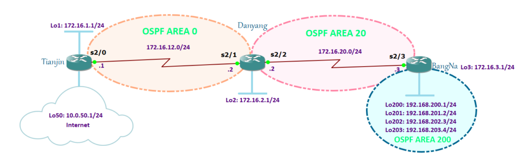
There are 3 areas in this lab: area 0, area 20 and area 200. As per OSPF golden rule, areas should all be connected to area 0. On this diagram, area 20 comply with this rule while area 200 does not.
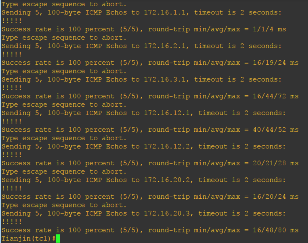
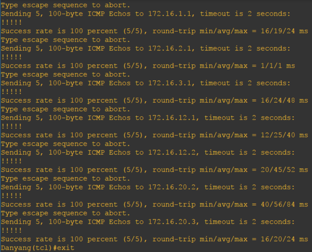
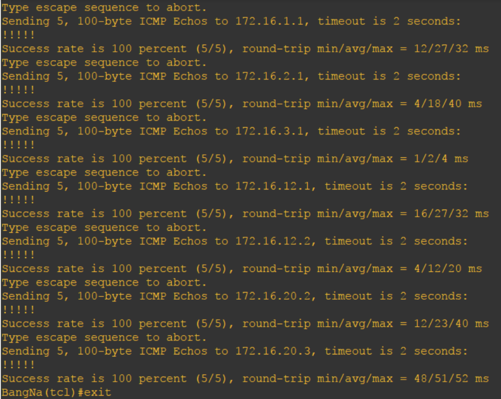
I have configured the basic OSPF configuration connectivity for Tianjin, Danyang, and BangNa routers. Pings are successful except for loopback200 – 203 because I haven’t added the said area.
BangNa#conf t
 Enter configuration commands, one per line. End with CNTL/Z.
 BangNa(config)#router ospf 3
 BangNa(config-router)#network 192.168.200.0 0.0.3.255 area 200
 BangNa(config-router)#exit
 BangNa(config)#int lo3
 BangNa(config-if)#ip ospf network point-to-point
 BangNa(config)#int range lo200 - 203
 BangNa(config-if-range)#ip ospf network point-to-point
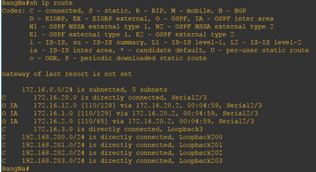
Now that area 200 has been added to BangNa router and since it is not connected to area 0 but connected to area 20, this what happens:
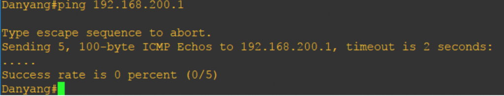
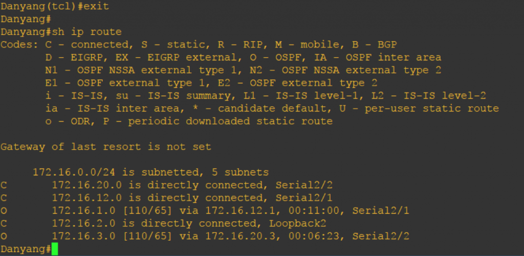
Danyang doesn’t know how to go to the 192.168.200.1 because it is not on its routing table. This is what I’m talking about earlier, if it is not connected to area 0 then they will not exchange routes for that area. There are no area 200 routes on the ABR so to fix this let’s use a virtual link.
Before using a virtual link, you must know the router IDs. I did not hardcoded the router ID so let’s make use of show ip ospf, show ip protocols, or show ip ospf interface to know the router IDs.
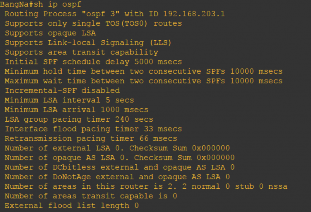
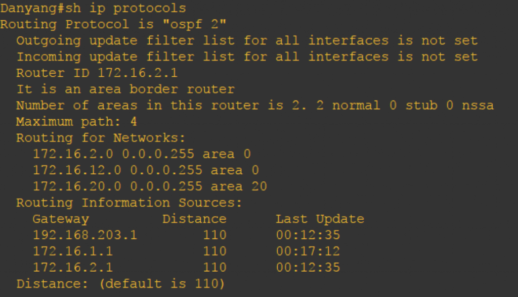
Looking at Danyang router, it’s router ID is 172.16.2.1 while BangNa has router ID of 192.168.203.1. When I first learned about the virtual link, I thought we could just make use of loopback IP and should be active and configured. I’m wrong. The physical IP address is also allowed and even the IP is not active nor configured on any interface as long as it is configured as router ID, it should work.
BangNa(config)#router ospf 3
BangNa(config-router)#area 20 virtual-link 172.16.2.1
BangNa(config-router)#
*Oct 19 15:50:43.235: %OSPF-5-ADJCHG: Process 3, Nbr 172.16.2.1 on OSPF_VL0 from LOADING to FULL, Loading Done
BangNa(config-router)#end
BangNa#
*Oct 19 15:50:53.675: %SYS-5-CONFIG_I: Configured from console by console
BangNa#conf t
Enter configuration commands, one per line. End with CNTL/Z.
BangNa(config)#router ospf 3
BangNa(config-router)#router-id 192.168.204.1
I changed my BangNa router ID from 192.168.203.1 to 192.168.204.1.
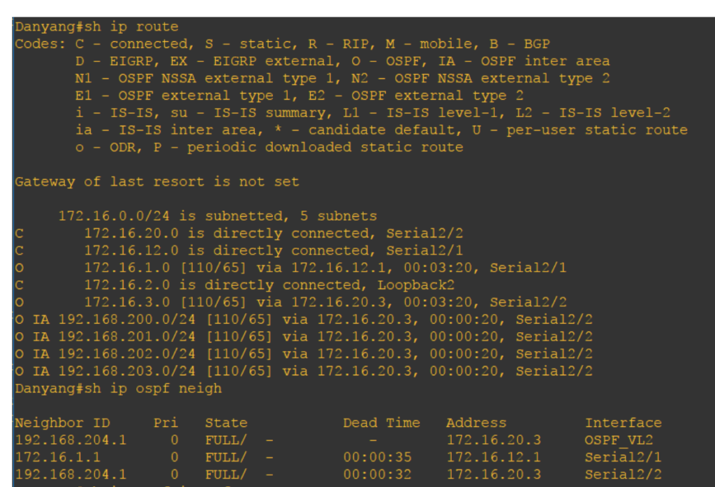
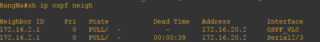
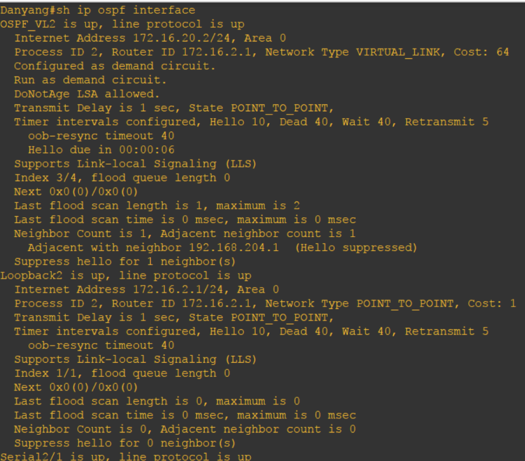
There are two same router IDs on both BangNa and Danyang routers. One is for the area 20 and the other one for the virtual link as indicated with “OSPF_VL” interface. You can also check it via “show ip ospf interface.”
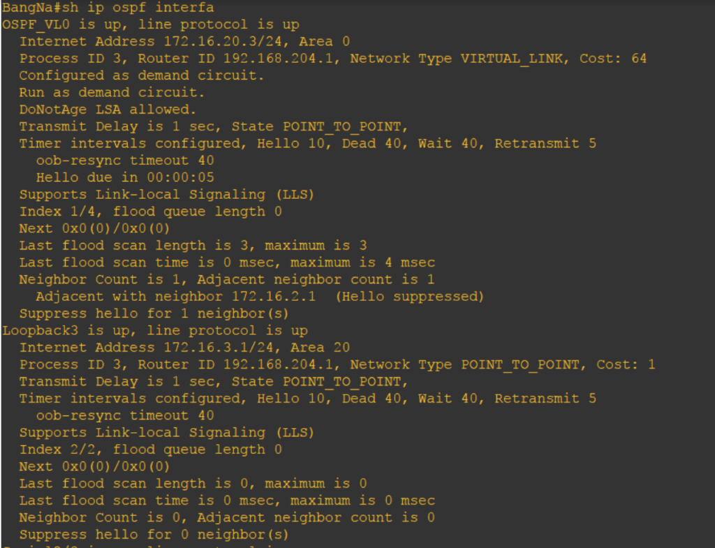
BangNa’s router ID, 192.168.204.1, is configured as point-to-point and virtual link network type.
Same goes with Danyang.
Amazing right? Now that there is virtual link configured, area 200 is somehow logically connected to area 0. Danyang and Tianjin can now ping routers from this area.
(Sigh) Virtual link is such a remedy on broken OSPF design. I was just thinking that if love has this kind of technology, there will be no broken hearts in the world.
]]>
I just had a break after finishing the Stub Area lab. Yeah, I ate a lot today. One whole chicken chop with Naples’s aglio e olio, crunchy pork knuckle, bitter gourd salad, and banana shake. After a heavy meal, I became drowsy. Then, I sipped 2 cups of Cafe Latte. And, I think I am back. I’m good and I can still count from 1 to 10.
We are back with OSPF areas discussion and this time we will tackle about the Totally Stubby Area. You have to pronounce it right though if you know what I mean.
Totally Stubby Area is a Cisco proprietary feature which works like a Stub Area but a stricter area type. If Stub Area do not allow certain LSA Types like Type 4 and Type 5 LSAs, Totally Stubby area do not allow it as well plus no Type 3 LSA too. The result is even smaller routing table.
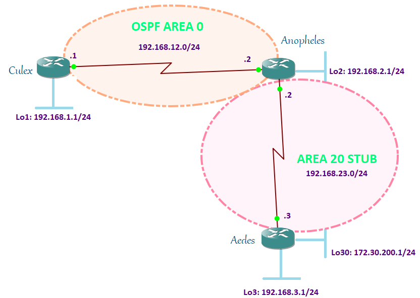
To configure Totally Stubby area, we have to add the “no-summary” command after the “stub” command. And, this should be done on the ABR only and not to the routers inside the Totally Stub area. Since my ABR is Anopheles router, I am going to do it here and Aedes stays with my previously configured “stub” command.
Anopheles#conf t
Enter configuration commands, one per line. End with CNTL/Z.
Anopheles(config)#router ospf 2
Anopheles(config-router)#area 20 stub no-summary
Anopheles(config-router)#end
Anopheles#

Anopheles#conf t
Enter configuration commands, one per line. End with CNTL/Z.
Anopheles(config)#router ospf 2
Anopheles(config-router)#area 20 stub
Anopheles(config-router)#end
Anopheles#
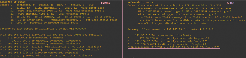
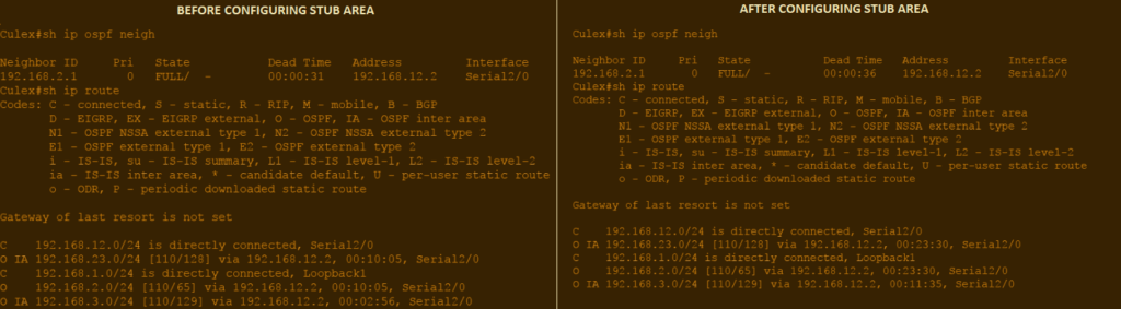
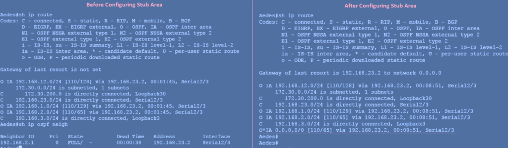
On the left is the Stub area result when doing show ip route while on the right is right after we configured it as Totally Stubby area. What did you notice on the routing table? There are no Inter-Area (IA) routes or Type 3 LSA. It converted it with the default route going to the Anopheles router.
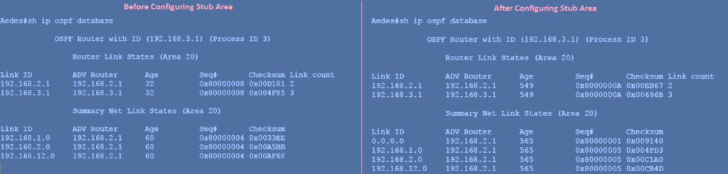
Let’s check the difference between a Stub and Totally Stub database:
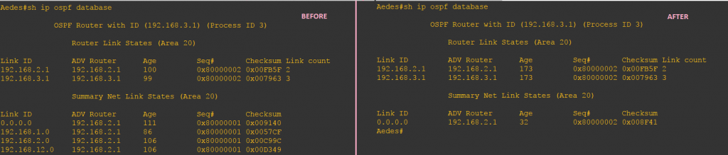
Totally Stub restricts Type 3 LSA and only allow a default route. The 192.168.1.0, 192.168.2.0, 192.168.12.0 are gone and all that’s left is the default route.
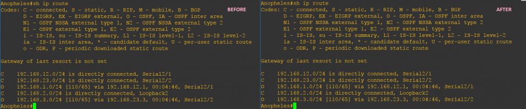
The routing table of Anopheles doesn’t make any difference.
Looking at the database, there is a change like what happened to Aedes router. Of course, they have the same database because they are in the same area.
Let’s check how we can confirm that the area type is Totally Stubby area:
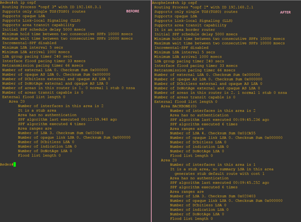
Aedes still showing as a stub area but the Totally Stubby area can be identified on Anopheles. It is showing that it is also a Stub area but there are no-summary LSA which confirms that our area 20 is a Totally Stubby area.
| LSA Types Allowed | LSA Types Not Allowed |
| Type 1 and Type 2 | Type 3, Type 4 and Type 5 |
Our topic for today is not about Sergeant Stubby but how a Stub network can be not so stubby. Isn’t it exciting?
Not-So-Stubby Area (NSSA) behaves like Stub area. It allows Inter-Area (O IA), Intra-Area, and default routes. LSA Type 1, Type 2, Type 3 are allowed but unlike the Stub area, External LSAs are allowed in NSSA area. External LSA in an NSSA area is not using Type 5 LSA but Type 7 LSA. Type 7 LSA tricks the OSPF area but in fact, it is the same as a Type 5 LSA. Type 5 LSA cannot propagate through an NSSA area and in order to do that a Type 5 to Type 7 translation (vice-versa) is being done by the ABR. Thus, it allows routes to be redistributed from an ASBR into that area with the use of Type 7 LSA.
In any case, the router in your Stub network needs to be connected to a new external network, then you need to configure it as NSSA. As discussed in my previous post, a Stub network will not be able to redistribute the routes as External LSA.

Let us redistribute Loopback 30 into Aedes and assigned both Aedes and Anopheles as NSSA network.
Aedes(config)#router ospf 3
Aedes(config-router)#no area 20 stub
Aedes(config-router)#area 20 nssa
Aedes(config-router)#area 20 nssa
Aedes(config-router)#redistribute connected subnets
Aedes(config-router)#end

Anopheles#conf t
Enter configuration commands, one per line. End with CNTL/Z.
Anopheles(config)#router ospf 2
Anopheles(config-router)#no area 20 stub
Anopheles(config-router)#area 20 nssa
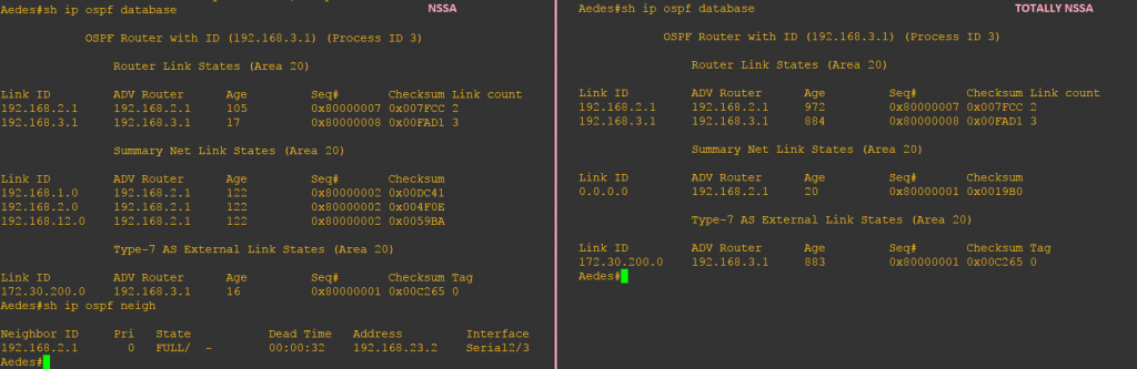
Now that we have done redistribution, the routing table and database for Culex are changed:
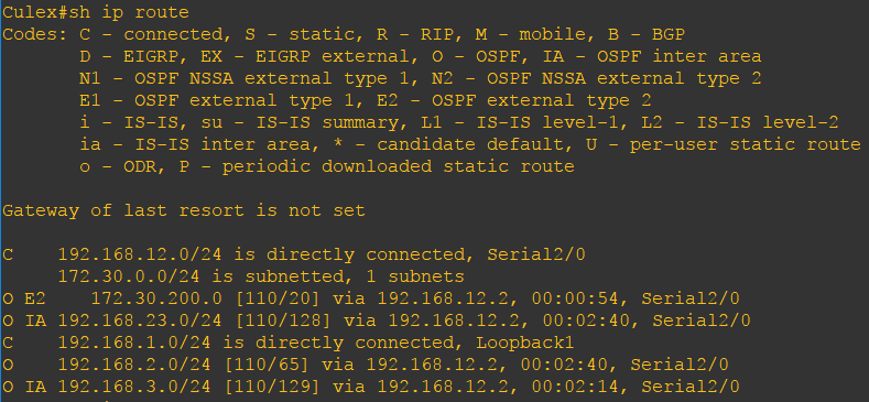
Culex learned external network 172.30.200.0 via Anopheles and tagged it as O E2 in the routing table. OSPF External Type 2 metric is the default since we did not configure it manually.
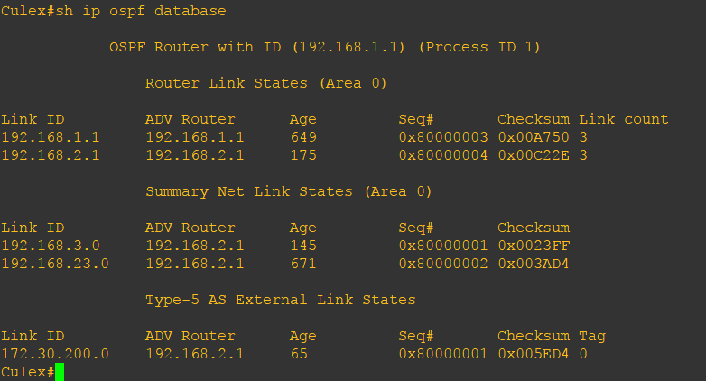
And finally, we got Type 5 LSA in the Culex routing table with 192.168.2.1 (Anopheles router ID) as the advertising router.
Let’s check what happened to Anopheles routing table and database.
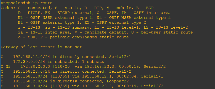
It has learned the external network 172.30.200.0 and tagged it as “O N2.” In Culex, it is tagged as “O E2” because the router is not in NSSA Area, unlike Anopheles.
The Anopheles database should match exactly with Culex and Aedes.
.Going to Aedes, let us check the routing table and the database.
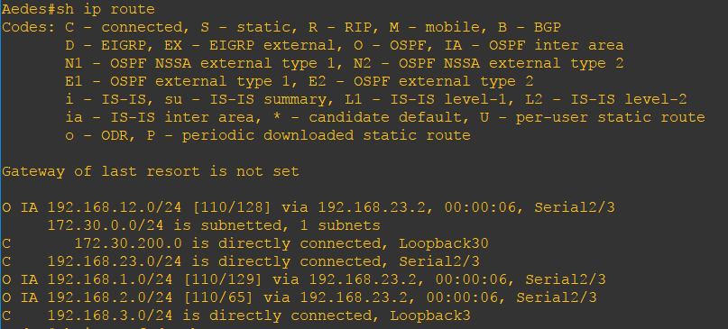
It has the same routing table as when we configured it is a stub. However, notice that there is no default route for Inter-Area. Why there is no default route being injected to the Aedes router automatically like what Stub does? It is how OSPF NSSA is designed. You can never argue if it is really how it is designed. However, this opens up another big discussion as it is all about the OSPF route preference which is the way OSPF calculates SPF and chooses the best path. For now, let be like that but if you still insist to have the default route, you can actually explicitly enter this command in the ABR:
Anopheles(config)#router ospf 2
Anopheles(config-router)#area 20 nssa default-information originate
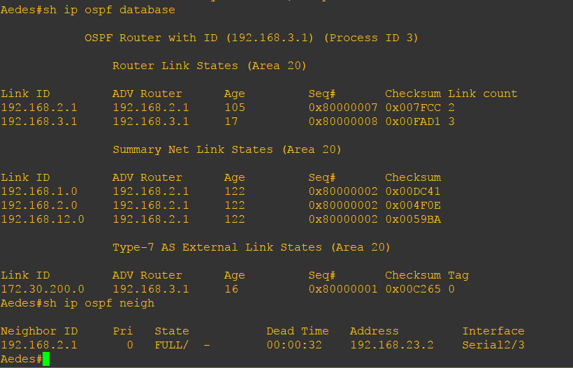
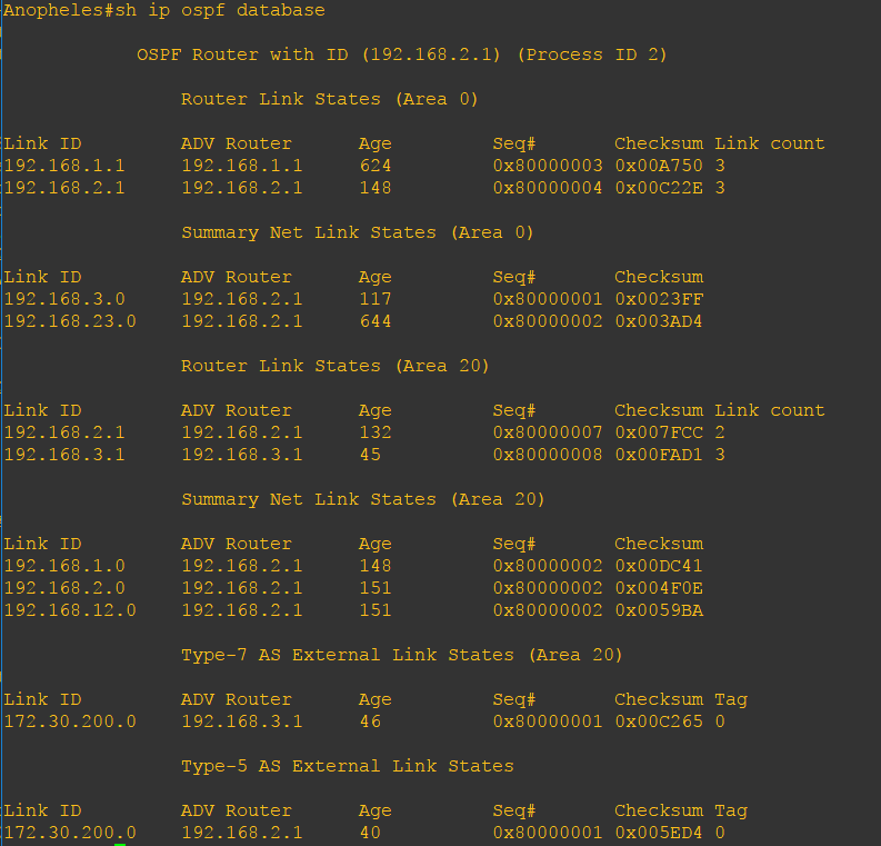
As you can see, there is no Type 5 LSA but only Type 7 LSA. Its database is exactly the same as Anopheles.
| LSA Types Allowed | LSA Types Not Allowed |
| Type 1, Type 2, Type 3, Type 7 | Type 5 |
I will use the same lab in my previous post. I just changed the configuration on the Anopheles router and put the “no-summary” command.
Anopheles#conf t
Enter configuration commands, one per line. End with CNTL/Z.
Anopheles(config)#router ospf 2
Anopheles(config-router)#area 20 nssa no-summ
Anopheles(config-router)#area 20 nssa no-summary
Anopheles(config-router)#end

Aedes(config)#router ospf 3
Aedes(config-router)#no area 20 stub
Aedes(config-router)#
Aedes(config-router)#area 20 nssa
It would be better to check the differences between NSSA and Totally NSSA using the before and after the output of the NSSA configuration.
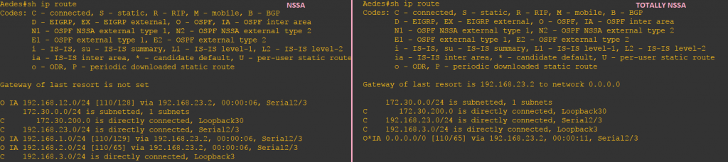
Unlike NSSA, Totally NSSA once configured on the ABR, will automatically inject the default route to advertise Type 3 LSAs. So, there is no need to explicitly configure it. Am I repeating the same thing?
Just like what happened in the Totally Stubby Area database, Type 3 LSAs are restricted and all that is left is the Type 1 LSA, Type 7 LSA and the default route advertised by 192.168.2.1.
| LSA Types Allowed | LSA Types Not Allowed |
| Type 1, Type 2 | Type 7 |
My posts regarding OSPF Area types are not yet done. If you will take a closer look, there are many things that I haven’t touched yet or clarified yet. Like if you check the database output, why some LSAs are missing even though it is allowed in this kind of area? This is going to be another discussion in my future posts.
]]>It is very easy to understand Stub Area if you are going to configure and apply it in the laboratory. A few years ago, what I did is just memorize the concepts of OSPF Stub Area. But after being away from the Academy for so long, my own brain failed to store my memories about it. As we all know the brain is flexible in storing lots of lots information about what you’ve learned, experienced, your everyday life since birth, and so on. However, it is not a reliable storage most especially if you are not doing it every day (And it is not that quite memorable enough to be remembered).
One day, I was asked by an Erudite about the Stub Area.
“What is that again?” I asked my brain.
My brain whispered, “Uhm… I don’t know… I think there is nothing special on it.”
“What on bits-and-bytes!”
Analyzing the routing table and the result after configuration will help you understand the Stub area better than reading it a hundred times.

Assuming that you have configured the interfaces and the OSPF adjacencies are established on each router, let us configure Aedes router and Anopheles router as part of the Stub Area:
Aedes#conf t
Enter configuration commands, one per line. End with CNTL/Z.
Aedes(config)#router ospf 3
Aedes(config-router)#area 20 stub
Aedes(config-router)#end


Anopheles#conf t
Enter configuration commands, one per line. End with CNTL/Z.
Anopheles(config)#router ospf 2
Anopheles(config-router)#area 20 stub
Anopheles(config-router)#end
Anopheles#
Easy?
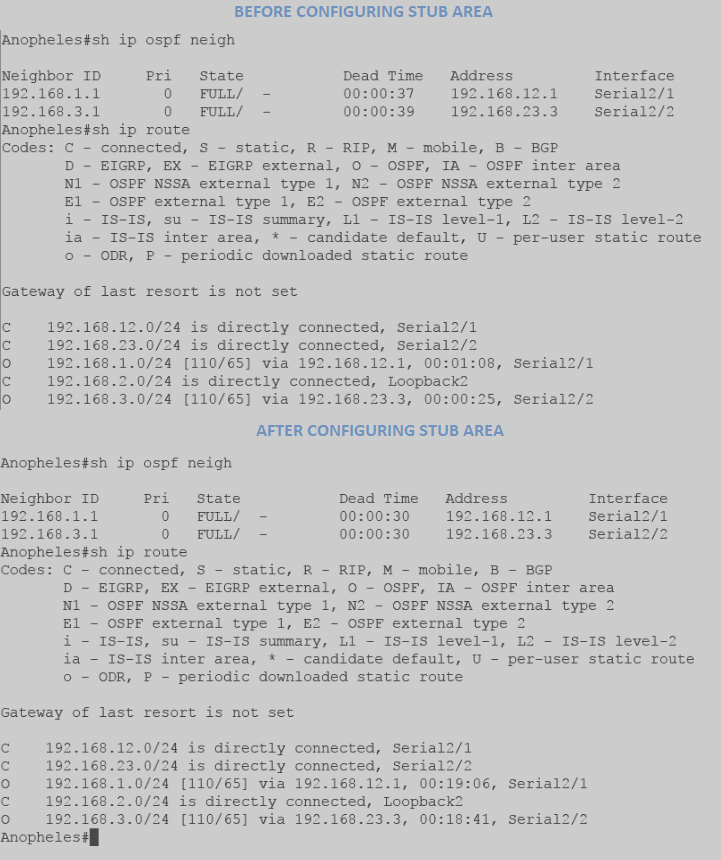
Now, this is the fun part. Let’s take a look at the routing tables of each router before and after we configure Aedes and Anopheles routers as stub.
The output above is captured from Culex. Culex’ neighborship with Anopheles is still up. The loopback network address of Anopheles, 192.168.2.0 (appearing as “O“), is learned by Culex through the directly connected interface address 192.168.12.2 of Anopheles. Aedes network 192.168.3.0 and the 192.168.23.0 network configured between Aedes and Anopheles appeared as “O IA” before and after Aedes and Anopheles are configured as Stub Area. Therefore, since Culex is in Area 0 and not configured as part of Stub Area, it’s routing table did not change after I configured Aedes and Anopheles router as part of Stub network.
The same goes with its database:
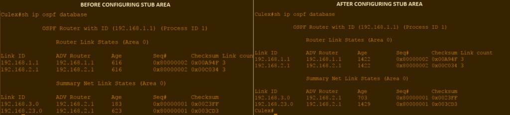
Router Link State (LSA Type 1) shows router IDs of Culex and Anopheles, while the Summary Net (LSA Type 3) shows the 192.168.3.0 and 192.168.23.0 network being generated and advertised by Anopheles.

If you are thinking that there are some changes on the Anopheles router, we’ll there is none on the routing table and OSPF adjacencies.
Before and after screenshot shows that Anopheles is still converged with Culex and Anopheles and the routing table still shows that there are 3 directly connected links and 2 OSPF neighbors (192.168.1.0 and 192.168.3.0).
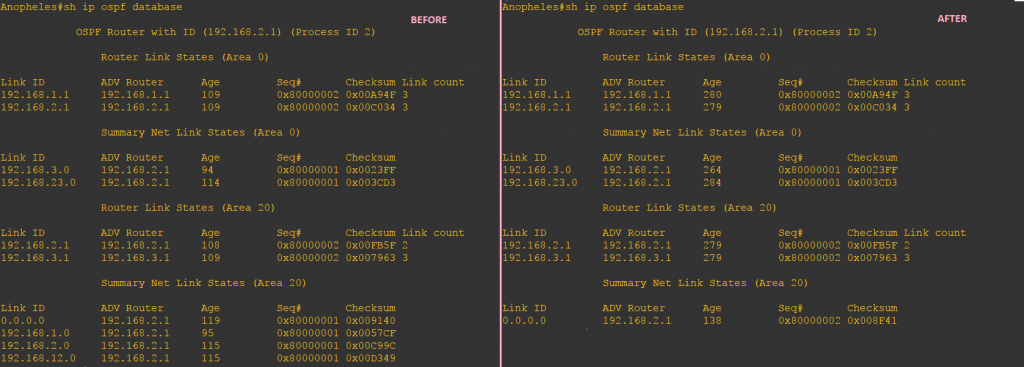
However, the Anopheles database has changed. The Summary Net Link States(LSA Type 3) now shows the default route 0.0.0.0 being advertised to the Aedes router.
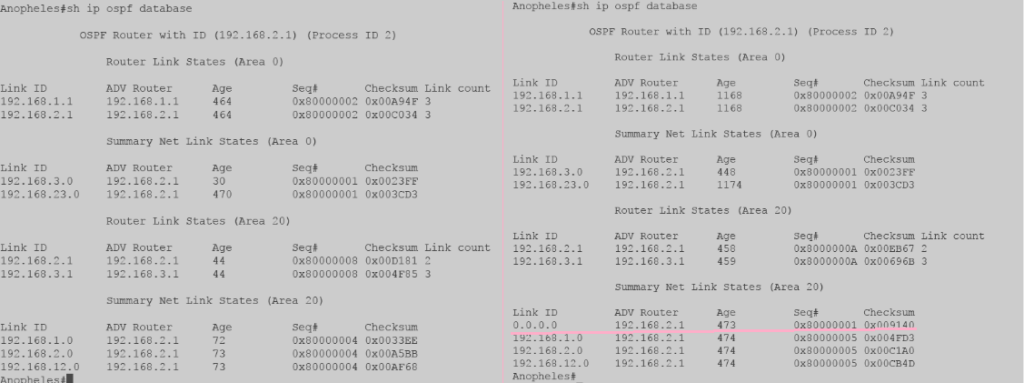
Looking at the Aedes router, though the neighborship is still the same, its routing table is changed after it was configured as part of Stub Area network. A Type 3 LSA is injected into the area by Anopheles to act as a default route. This allows Aedes to connect to other routers outside the stub area.
Lastly, what did you notice on the database of each router? Aren’t they the same?
Anopheles, since it is the ABR, has the database of both Area 0 and Area 20. It has the same database with Culex in Area 0 and same database with Aedes in Area 23. We, therefore, conclude, that it is true that OSPF maintains the same database in each area. Amazing, right?
]]>
According to Cisco, OSPF area is a collection of logical OSPF networks (routers and links) that have the same area identification. Depending upon the design of your network, your routers can be part of a single area or multiple areas. Why do we have to complex things and put the router in different areas? Actually, there are many reasons, and one of the many reasons is that it reduces the size of OSPF database when OSPF network is divided into different areas. Think of it this way, dividing the routers into different areas, reduces the size of the database, reduces the frequency of SPF calculation and smaller routing table. Thus, fewer requirements on router memory and CPU. I am not saying that SPF calculation is exhausting the CPU and router memory but the sending and flooding of the new topology information does.
OSPF AREA TYPES
No matter what your OSPF design in your network, all areas you have created should be connected to the backbone area. Backbone area or Area 0 (0.0.0.0) is like the meeting points of all these non-backbone areas. So, it is not just an option or recommendation but a must in every OSPF network design. Although there is an option called virtual link, it is not a good network design but just a remedy to a broken OSPF design.
Now, not all LSA Types are allowed in different areas. Some LSA Types are restricted and depend upon which area type is configured. This further reduces the link state database and routing tables. Injecting too many external routes are also memory intensive. However, all LSA types are allowed in the Normal area. An area which is not configured as Stub, Totally Stub, NSSA, NSSA Totally Stub area is called Standard/Normal Area. We can say that the backbone area is behaving like a Normal /Standard Area as LSA Type 1-5 are not being restricted in this area. When the network is divided into different area numbers (non-zero), an ABR is used to connect the Standard area to the Backbone Area.
On my next post, I will introduce some of the area types which have their own rules in restricting LSA Types.
]]>